 |
Thermal Camera SDK 10.0.1
SDK for Optris Thermal Cameras
|
|
Thermal Camera SDK 10.0.1
SDK for Optris Thermal Cameras
|
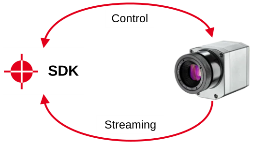
When connecting to a thermal camera the SDK establishes two separate communication channels:
Depending on your chosen connection type, USB or Ethernet, these channels use different protocols/mechanisms to transfer data. In the case of Linux this may also depend on the type of your device.
The data stream from the device is uncompressed for both the USB and Ethernet connections. Please keep this in mind because this poses some demands on your USB and network hardware especially if you are operating multiple devices at once.
Another hardware requirement to be aware of is the power draw of the devices when connected via USB. This is typically not an issue with your average computer or laptop but can pose a limiting factor when working with embedded devices.
The SDK uses the Human Interface Device protocol (HID) to send commands to your device. The HID protocol is, for example, used by input devices like your mouse and keyboard.
Once you connect a device to your computer via USB it is recognized by the operating system as a USB camera. You can access its data stream with programs like the VLC media player or guvcview. When you open it as a capture device you will, however, get something like this:
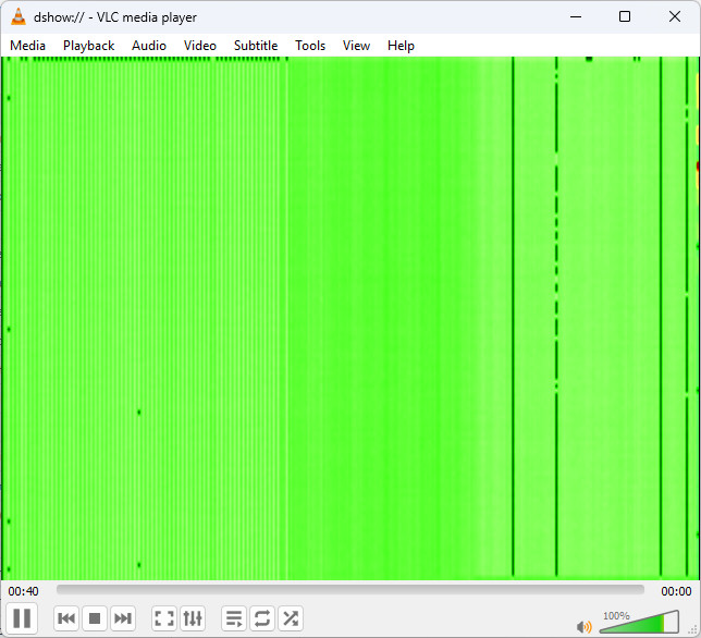
There are several important points to note:
bandwidth in bytes per second = (width x height x 2) / framerateAs an alternative, you can take a look at the format definitions file. It is a text file that contains all the available video formats for the different device types. It specifies the output formats Out with their corresponding input formats In as a tuple of in the form of width height framerate.
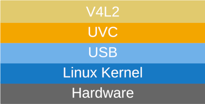
The devices use two different USB transfer methods to stream the thermal data:
This has no implications on Windows since the used Direct Show layer seamlessly supports both transfer modes. On Linux, however, the default Video for Linux v2 (V4L2) kernel driver for such applications just supports isochronous USB data transfer. Because of this the SKD accesses the data stream of the bulk transfer devices through the lower level USB kernel driver instead of V4L2. This is also the reason why you are not able to open their data streams with programs like the VLC player.
Before you can use your Ethernet capable device you first have to adjust the on-device configuration to your network environment. Please note, that this configuration can only handle static IP addresses. To set the configuration you need the following pieces of information:
You can either utilize the tool otc_configure_ethernet or the PixConnect to change these on-device settings.
From the perspective of the machine running the SDK the following network connections are established:
<Device IP>:2000.<Device IP> on the <Destination Port>.Please make sure that any firewall on the machine allows these connections.
In order to send commands to your device and to retrieve small bits of information the SDK establishes a TCP to the device IP address specified in the configuration file. It will always address the port 2000 on the device.
2000 is required by the firmware and can not be changed by the SDK.Once the device is powered and its firmware is running it tries to locate the configured destination IP address. On success it starts sending the thermal data via UDP datagrams to the set destination socket (destination IP address + destination port). Typically, a thermal frame is comprised out of multiple datagrams that are pieced together by the SDK.
As mentioned before the data stream is uncompressed and thus poses some demands on the network hardware. To clarify those Optris released technical notes detailing the Network Requirements for Optris Imager in Industrial Applications.